
Hydraulic Cylinder Manufacturing Guide: Process, Materials, Tolerances & Testing
If you need to specify, buy, maintain or refurbish a hydraulic cylinder, this guide gives you the manufacturing basics—clearly. You’ll learn what happens at each stage (machining, honing, sealing, assembly and pressure testing), what “good” looks like, and the common mistakes that cause leaks, drift and premature wear.
Built to support the hydraulic cylinder manufacturing expertise of Completely Hydraulic. Contact us if you want help specifying a cylinder build.
Quick answer: how are hydraulic cylinders manufactured?
Hydraulic cylinders are manufactured by machining the major components (barrel, rod, piston and gland), preparing the internal bore (often by honing), installing the sealing and wear system, assembling in controlled conditions, and pressure testing to confirm leak-free operation and correct performance.
Guide contents
Use this to jump to the exact part you need. Each section is written for fast, practical understanding.
gland, rod, piston, seals, barrel 2) Manufacturing process
machining → honing → assembly 3) Materials & finishes
rod plating, barrel tube, corrosion 4) Tolerances & quality
fits, alignment, surface finish 5) Seal systems
rod seals, piston seals, wiper 6) Pressure testing
what gets tested and why 7) Common failures
leaks, drift, scoring, bending 8) Specification checklist
what to provide for a build
1) Hydraulic cylinder parts explained (plain English)
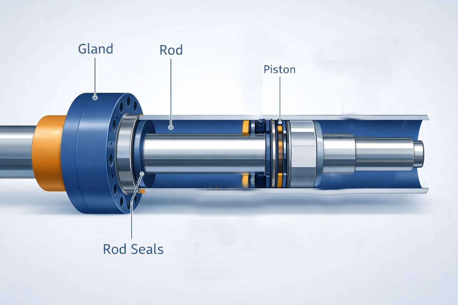
Most hydraulic cylinders share the same core components. Understanding what each part does helps you diagnose problems faster and specify a replacement correctly.
Gland
Houses the rod sealing system and guides the rod. Often includes the wiper and primary rod seal locations.
Rod
The chrome (or coated) shaft that transfers force out of the cylinder. Surface finish and hardness are critical.
Piston
Divides the barrel into pressure chambers. Fitted with piston seals and wear rings to control leakage and guidance.
Rod seals & wiper
Keep oil inside and contamination out. A damaged wiper often leads to rod scoring and rapid seal wear.
Piston seals
Control bypass across the piston. Poor sealing here commonly causes drift, loss of force and heat build-up.
Barrel
The tube that contains pressure. Bore condition (honing, finish, straightness) strongly affects sealing and life.
2) The hydraulic cylinder manufacturing process (step-by-step)
Exact methods vary by design (tie-rod, welded, telescopic), but the manufacturing logic is consistent. Here’s a practical, high-level workflow you can use to understand lead times, costs and quality.
- Confirm design and specification. Bore, rod, stroke, mounts, ports, working pressure, duty cycle, environment and oil type.
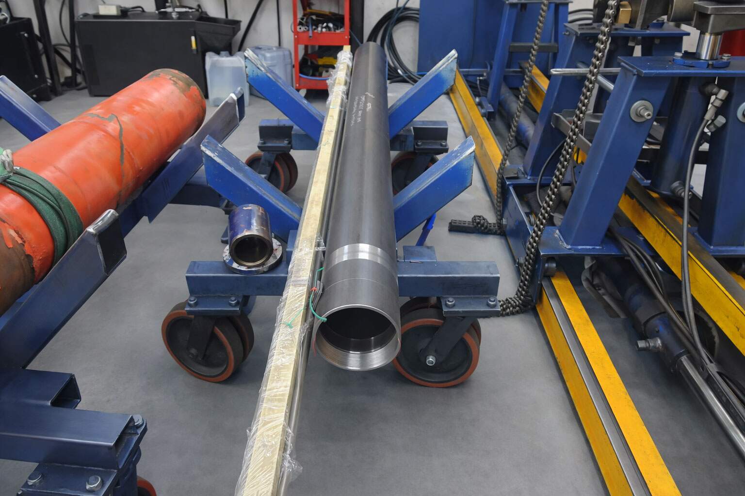
- Prepare the barrel. Cut to length, machine end interfaces, then prepare the internal bore (often by honing) to the required surface finish.
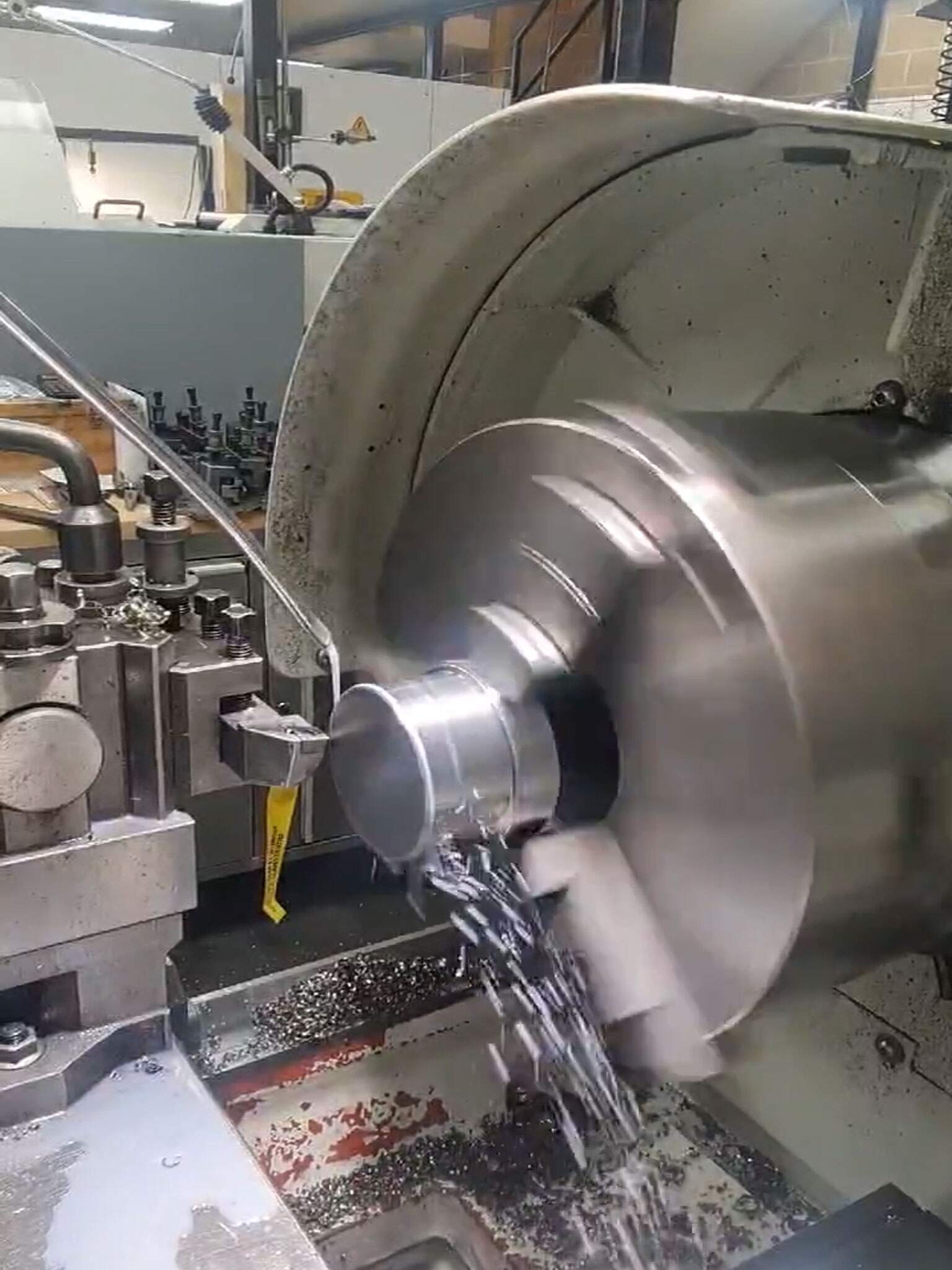
- Machine the rod. Turn, grind and finish the rod to spec. If plated/coated, confirm thickness and finish suitable for the seal system.
- Machine piston and gland components. Create seal grooves, wear-ring lands, threads, ports and mounting features.
- Cleanliness and deburr stage. Remove burrs and sharp edges, then clean thoroughly—contamination is a seal killer.
- Build the seal system. Install rod seals, wiper, piston seals and wear rings. Confirm correct orientation and compatibility.
- Assembly. Assemble to the correct fits and clearances; confirm smooth movement and correct torque/locking methods.
- Pressure test and functional checks. Verify external leaks, bypass, movement, and hold under pressure before dispatch.
3) Materials & surface finishes (why they matter)
Cylinder life is heavily influenced by material selection and finish quality—especially on the rod and the barrel bore. The “right” choice depends on corrosion risk, contamination risk, pressure and duty cycle.
Barrel / bore
- Honed tube bore finish helps seals bed in and run cooler.
- Out-of-round or rough bores accelerate seal wear and bypass.
- Corrosive environments may require upgraded materials or protection.
Rod
- Surface finish affects seal life and leak risk.
- Coating/plating selection should match the environment.
- Rod scoring is often contamination + poor wiping, not “bad luck”.
4) Tolerances, alignment & build quality
Many “mystery failures” come down to alignment and tolerances. A cylinder can be built from good materials and still fail early if guidance, clearances and concentricity are not controlled.
Fits & clearances
Seal grooves, wear rings and guidance surfaces must match the seal system—too tight runs hot, too loose bypasses and leaks.
Alignment
Misalignment side-loads the rod, damages bearings and scores surfaces. Good mounting design reduces side-load.
Cleanliness
Debris during assembly is a common root cause. Clean build practices improve seal life dramatically.
5) Seal systems: rod seals, piston seals, wear rings & wipers
Seal choice isn’t just “pick a kit”. Temperature, oil type, speed, pressure, contamination and side-load all influence which seals and materials make sense.
Rod end sealing (outside world)
- Wiper: first defence against grit and moisture.
- Primary rod seal: keeps pressure in.
- Secondary / buffer: stabilises pressure spikes and reduces weep.
Piston sealing (internal control)
- Piston seal: prevents bypass across chambers.
- Wear rings: guide the piston/rod and reduce metal-to-metal contact.
- Symptoms of bypass: drift, loss of force, heat.
6) Pressure testing: what should be tested before installation?
Testing confirms the cylinder is safe, leak-free and functioning as expected. The exact procedure depends on the design and application, but good testing generally checks external leakage, movement smoothness and pressure holding.
Leak test
Check gland, ports, welds and end caps under pressure.
Functional stroke
Confirm smooth movement, correct stroke, and no binding.
Hold / bypass check
Confirm minimal internal bypass (drift) where relevant.
7) Common hydraulic cylinder failures (and likely causes)
When you know the pattern, most failures are predictable. Here are the typical symptoms and what they usually point to.
External leaks
Rod seal wear, contamination, damaged rod surface, incorrect seal selection or assembly damage.
Drift / creep
Piston seal bypass, worn wear rings, bore issues, or valve/system issues (always confirm system too).
Rod scoring
Wiper failure, contamination, poor rod finish, misalignment/side-load, or damaged guidance.
8) Hydraulic cylinder specification checklist (copy/paste)
If you want a cylinder manufactured (or a correct OEM replacement), providing the right information saves time and prevents expensive rework. Copy this checklist into an email or job sheet.
Core dimensions
- Bore size
- Rod diameter
- Stroke length
- Closed length / open length (if known)
- Mounting type (clevis, eye, trunnion, flange, etc.)
Performance & environment
- Working pressure (and any spikes)
- Load / duty cycle (light, medium, heavy)
- Oil type and temperature range
- Environment (dust, mud, salt spray, washdown)
- Port sizes and locations
Need a cylinder built or refurbished?
Hydraulic Online is the knowledge hub. For real-world cylinder manufacturing support, Completely Hydraulic can build OEM replacements and bespoke cylinders—plus full ram repairs, reseals and rod replacements.
- OEM replacements and bespoke cylinder builds
- Rod replacements, reseals and full ram rebuilds
- Pressure testing and certification available
- Cylinder builds are performed in the Essex depot and shipped anywhere in the UK
Hydraulic cylinder manufacturing FAQs
How long does it take to manufacture a hydraulic cylinder?
It depends on specification, material availability and machining workload. A like-for-like replacement can be quicker than a bespoke design, especially if mounts and porting are standard.
What is honing in hydraulic cylinder manufacturing?
Honing is a finishing process that improves the barrel bore surface and geometry. A good bore finish helps seals run smoother, reduces heat and improves service life.
Why do hydraulic cylinders fail early after replacement?
Common causes include contamination, incorrect seal selection, misalignment/side-load, poor rod condition, or tolerance issues that lead to heat and rapid wear.
What causes hydraulic cylinder drift?
Drift is often caused by internal bypass across the piston seals. It can also be influenced by system valves, so it’s worth confirming whether the cylinder or the hydraulic circuit is responsible.
What information do I need to specify a custom cylinder build?
Typically: bore, rod, stroke, mount type, working pressure, port sizes/locations, operating temperature, oil type and environmental conditions. Photos and measurements help if the original spec is unknown.